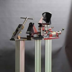
CORRECTING DEVICE
PUT - BENDING MACHINE
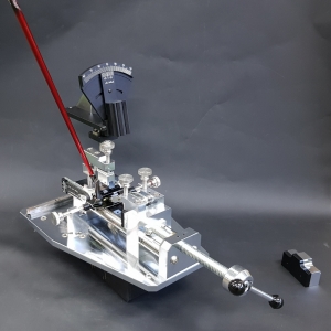
IRON BENDING MACHINE
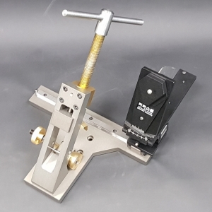
ANTI-S. BENDING BAR
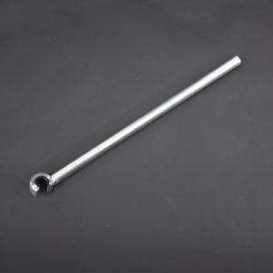
VA - HOT MELT MACHINE

CO - MACHINE FIXTURES
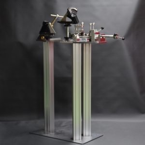
FITTERSLAB PUTTER BENDING MACHINE
FITTERSLAB Putter Bending Machine is a premium putter bending machine that
precisely measures the lie angle and loft angle of a putter and can perfectly correct them
without damage through a powerful and secure clamping structure.
In particular, designed for the first time in similar products to separately measure
the product's loft angle and the user's loft angle,
it is the only putter fitting equipment capable of measuring all technical elements
required for putter fitting
Among golf club fitting equipments,
the most incomplete and unreliable equipments are those related to putter measurement or correction.
This is because most equipments only measure the relative lie angle or loft angle based on the shaft,
and in particular, there has been no product that "perfectly fixes the putter without damage"
during correction work.
Given the characteristics of putter products where high-priced products are distributed,
this can be said to have been a very disadvantageous aspect for fitting work.
Main Features of the FITTERSLAB Premium Putter bending Machine
A. Application of Loft Angle Separate Precision Measurement Design
FITTERSLAB Putter Bending Machine is the world's first equipment
capable of independently measuring three angles.
Since the loft angle must be treated importantly in terms of fitting for a putter as well as the lie angle,
it is designed to separately measure the product's loft angle and the user's loft angle.
Existing products measure the angle of the head face surface relatively based on the putter shaft.
Since this measurement only measures the user's variable loft, there is a limit to putter fitting.
Precise putter fitting requires both the product's inherent loft and the user's variable loft together
FITTERSLAB Putter Bending Machine is the first product to apply a design that
separately measures the two loft angles.
B. Fixed Loft Measurement Function
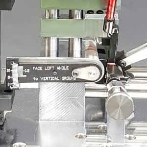
This is a function to measure the product's inherent loft angle given to the putter's head shape.
It is measured simultaneously with the variable loft
C. Variable Loft Measurement Function According to User's Setup
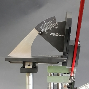
This is a measurement function of the variable loft angle made by the user's setup,
which can be combined with the inherent loft angle to calculate the actual loft angle applied to the user.
D. Lie Angle Measurement Function
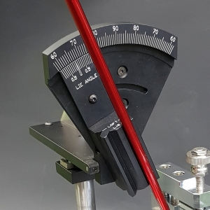
FITTERSLAB Putter Bending Machine is designed to measure the actual lie angle
according to the center line of the putter.
Therefore, an accurate lie angle is measured even if the topline is not parallel to the ground
or is not in a straight shape
E. Precision Measurement Capable in Units of 0.1 Degrees per Axis
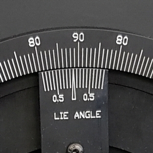
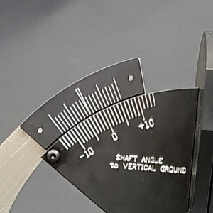
FITTERSLAB Putter Bending Machine applies a vernier method to precisely measure
in units of 0.1 degrees per axis.
.
This function, especially along with the LM system feed method for each axis,
always measures precisely without play.
And a play-preventing lubrication structure is applied to all rotating parts
to prevent measurement errors caused by wear or play even during long-term use
F. Design for Precision Measurement Applying LM Guides to All Measurement AxIs
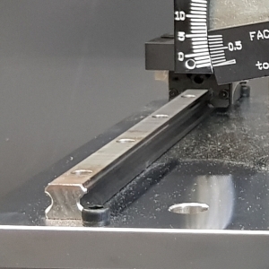
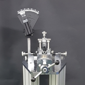
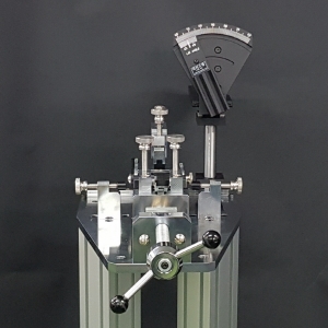
Just like FITTERSLAB's lie-loft bending machine,
FITTERSLAB Putter Bending Machine realizes superior measurement precision
by applying an LM guide system to all feed axis.
With a design structure incomparable to the ball bushing method in terms of
product precision and durability,
it guarantees very precise measurement as well as durability without play even after long-term use.
In addition, the LM system was applied to both the X and Y axes.
G. Application of Measurement Standards Based on the Shaft's Central Axis
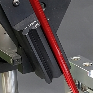
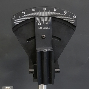
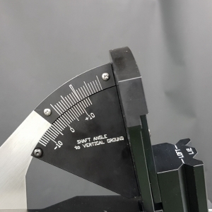
FITTERSLAB Putter Bending Machine is designed so that the center line of the shaft is measured
For the measurement of the center line, the loft angle and lie angle measurement surfaces are separated,
and this precision design is a precise method measured based on the axis
regardless of the shaft's taper rate or steps.
H. Structure with Separately Applied Fixing Parts for Measurement and Correction
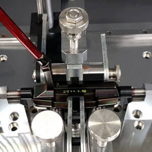
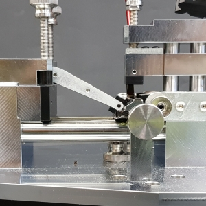
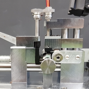
If measurement and correction work are performed concurrently with the same parts,
either precision or clamping strength may deteriorate.
To prevent this problem, FITTERSLAB Putter Bending Machine is manufactured to
simultaneously satisfy precise measurement and firm clamping by separating the supporting parts
for measurement and the parts for correction
I. Application of High-Strength Parts for Perfect Clamping
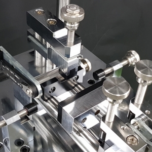
If even minor movement occurs in the clamping method of a putter bending machine,
it easily scratches the putter.
FITTERSLAB Putter Bending Machine processes clamping system parts with
hard chrome-plated iron materials to maintain strong clamping rigidity without minor movement.
Although hard chrome-plated parts incur higher manufacturing costs than
parts made of general aluminum materials,
their superior rigidity exerts a strong clamping force without minor movement.
FITTERSLAB's product pursues perfect rigidity by applying aluminum materials to
measurement-related parts and hard chrome-plated iron and stainless steel materials to
correction-related parts.
J. Application of Perfect Clamping Design Through Dispersion of Contact Points
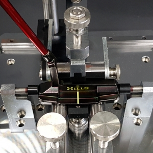
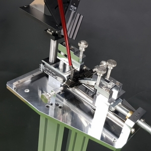
FITTERSLAB Putter Bending Machine fundamentally prevents putter damage
by dispersing the contact area into 8 points and forming contact points in a narrow area,
enabling strong and motionless clamping.
In addition, the contact surface with the putter applies a high-density resin material to prevent
the putter surface from being damaged fundamentally preventing putter damage
In other products, fixed contact points are simple and formed over a relatively wide area.
Due to the characteristics of putters with many three-dimensional curves,
this clamping method makes accurate clamping difficult and since firm clamping is not easy,
the putter is easily scratched.
This is the reason why Fitterslab's bending machine applied multiple support structures.
K. Main Clamping Bolt Ensuring Smooth Operation and Firm Clamping
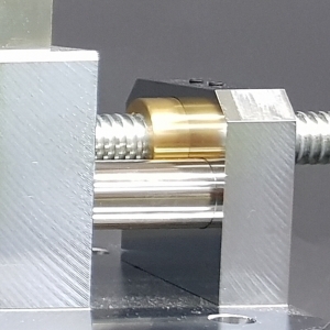
FITTERSLAB Putter Bending Machine applies a brass nut to the feed structure of the main clamping bolt,
securing smooth movement and durability, as well as clamping the putter without play.
L. Others and Precautions
*FITTERSLAB Putter Bending Machine has a wide and very heavy base plate,
making most work possible just by mounting it on a table.
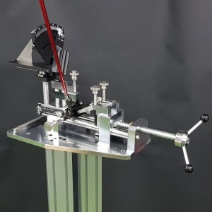
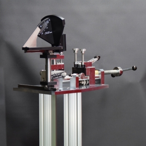
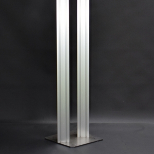
*When installing on a stand, please be sure to fix the floor securely
as there is a risk of injury due to the heavy weight of the product.
FITERSLAB IRON BENDING MACHINE
FITERSLAB Iron Lie and Loft Bending Machine is premium fitting equipment
featuring outstanding measurement performance and durability.
Designed with FITTERSLAB technology and manufactured in Korea
By combining the new concept of a single-part mainframe structure with a precision gauge of 0.1 degrees,
it delivers durability and measurement accuracy
without the need for additional measuring instruments.
It is also the first orthodontic device to apply zero-point measurement.
This high-performance device applies a gap-free LM system to each feed axis
to fully support precise measurement
Generally, it is said that a club's lie & loft angle must be measured on a lie-loft measuring machine,
and that correction (bending) work should be done on a bending machine
using the measured values as comparison values.
Considering existing products where simply machined parts are connected by bolts,
it is clear that this statement is not incorrect.
In that case, it is necessary to verify whether the measuring instrument provided with them is accurate.
Without the results of precision design and high-precision machining technology,
it is difficult to trust measurement accuracy.
A measuring device less accurate than a correction (bending) device,
A correction (bending) device more accurate than a measuring device...
This is why FITTERSLAB insists on in-depth design and high-precision machining
Main Features of the FITTERSLAB Iron bending Machine
A. Main Frame Integrated Without Connection Parts
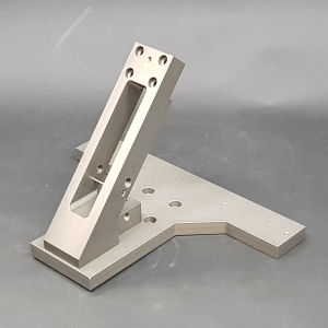
This is the part with the most prominent strength of FITTERSLAB's products.
The main body of FITTERSLAB Iron Bending Machine is machined into a high-precision integrated part,
so there are no bolts connecting it.
With the rigidity of the integrated structure eliminating the need for unnecessary auxiliary fixing devices,
it secures simple yet powerful fixing performance,
and is equipped with ultra-high hardness hardening treatment with rigidity stronger than iron
to achieve twist-free rigidity and durability.
B. Clamping Block Manufactured to Match Head Top Line Curvature
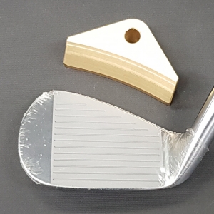
The clamping block is an important part that directly contacts and fixes the top line of the club head.
The clamping block of FITTERSLAB's product is machined with a 3-dimensional curvature that
brings the clamping surface with the club close to the top line shape of the head.
Designed such that contact points are formed plurally close to each frame or
contact occurs over a wide range, the clamping block is structured to prevent head deformation or damage
by widely and closely dispersing the load applied to the head's top line near the frame's contact points.
Unlike operations that involve high clamping pressure due to the nature of bending,
Although golf club materials have become softer recently,
the clamping blocks of other products have a two-dimensional machined structure that
supports the face from both sides and compresses the upper line at a single point in the center
In this structure, a problem arises where a large shear force acts on the face surface.
In particular, the recently released wedge models with replaceable head faces are a critical issue,
so extra caution is required.
C. Brass Sole Block and Head Adjuster Applying Large-Diameter Eccentric Design
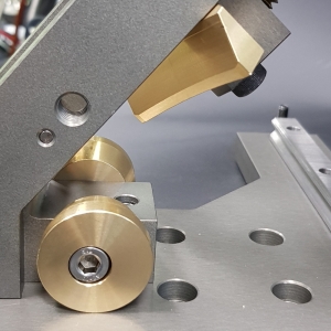
The sole block is the component that supports the sole of the club head.
The sole blocks used in FITTERSLAB Iron Bending Machine are made of brass to prevent
scratches on the club heads and feature a large diameter to secure firmly without back compression
In addition, by applying an eccentric design to the fixed center of both blocks,
Regardless of the clubhead’s various sole shapes, the centerline of the clubface can be adjusted
to be closer to the centerline of the device.
The head adjusters, which support the head’s level,
are also securely fixed using the same brass material and high-strength bolts.
D. High-Durability Clamping Lever Block and Precise Setting Guide Pin
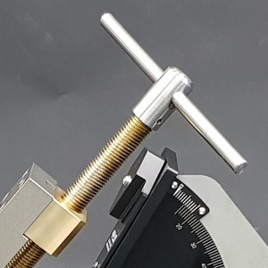
By machining and combining a wear-resistant brass nut block with a
spring supported high-rigidity lever bolt, smooth operation and durability are secured.
In addition, by securing sufficient frame rigidity,
FITTERSLAB Iron Bending Machine is designed with the width of the central part as wide as possible
to secure the widest possible viewing angle,
making it easy to check the horizontality of the head when fixing the club
Along with the circular guide pin for horizontal setting precisely installed in the center,
accurate horizontal setting of the head is achieved from any angle,
enabling precise measurement at the level of a measuring instrument.
E. Application of LM Guide System to Each X-Y Axis
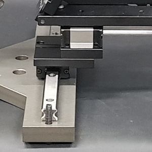
FITTERSLAB Iron Bending Machine apply high-cost LM guide systems to each feed axis, X and Y,
maintaining unmatched precision and durability compared to other products that
use bars and ball bushings.
F. Gauge Plate Converted Left and Right with Simple Movement
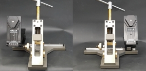
When changing directions between right-handed and left-handed clubs,
the gauge plate is pushed all the way back to simply switch directions.
(The gauge plate moves in a letter 'ㄷ' shape)
*However, since the adjuster is only on one side due to interference issues,
must loosen the bolt to change direction when switching
G. Gauge Capable of Precise Measurement in Units of 0.1 Degrees
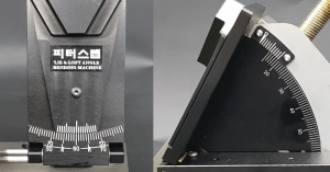
FITTERSLAB Iron Bending Machine enables precise measurement in units of 0.1 degrees
each through the application of a vernier-style scale,
and the gauge plate has its background treated with black anodizing to enhance visibility.
The measurement precision of FITTERSLAB Iron Bending Machine is also
a part that users say is more accurate than measuring instruments
H. First Zero-Point Check Function in Corrector Products
FITTERSLAB Iron Bending Machine is applied with a function that allows the user
to check the zero point for the first time among similar products.
Lie angle check:
Attach the side of the measurement gauge to the main body frame,
check the upper and lower gaps, and if the gap does not widen,---it is correct.
Loft angle check:
ith a right-angle square aligned to a right angle on the back of the gauge plate,
if the scale indicates 50 degrees,--- it is correct.
* Unless an abnormality occurs in the LM guide parts due to strong impact, etc.,
the zero point will not go out of alignment.
Since adjusting the zero point is a professional part,
adjustment is possible through AS application
I. Precautions When Using the Product
1. Since this product is a correction equipment having a measuring function,
a strong impact or the like on the measurement part can be a source of error.
In particular, please be careful not to apply impact when operating the gauge plate.
2. Initially, the LM guide may operate somewhat heavily,
so a certain period of break-in time may be required.
Separate lubricant injection is not required for the LM guide.
3. When bending, please be sure to detach the gauge plate from the club to protect the gauge before working.
4. Bending work with the club clamped loosely may cause frame wear, so tighten it firmly.
5. The stand of this product is supplied separately in freestanding and table-mounted forms,
so can select and purchase it.
(The base plate of the freestanding type can be selected between anchor type and footplate type).
6. Please be sure to wear safety goggles and safety equipment according to safety regulations when using
ANTI-SCRATCH HOZEL BENDING BAR
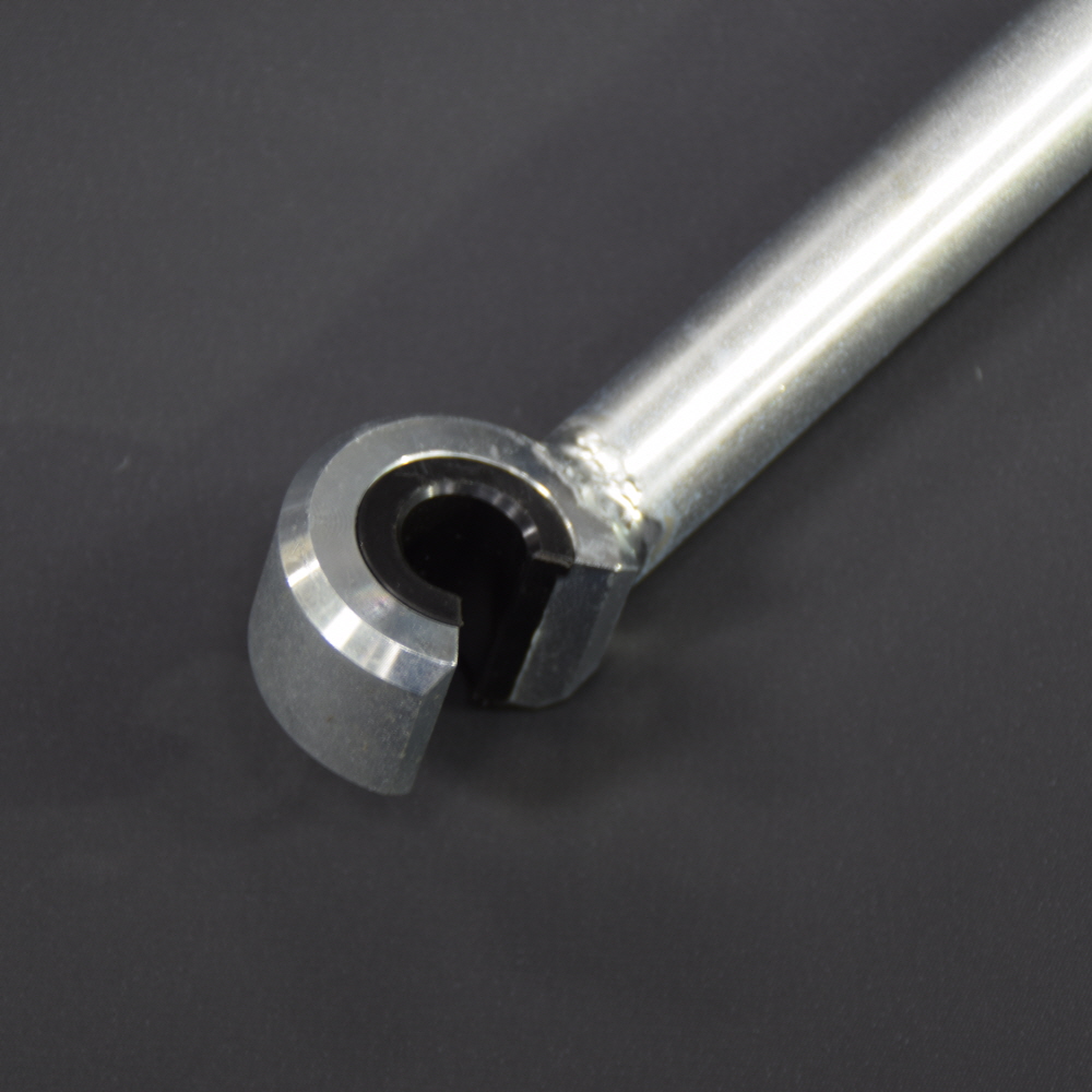
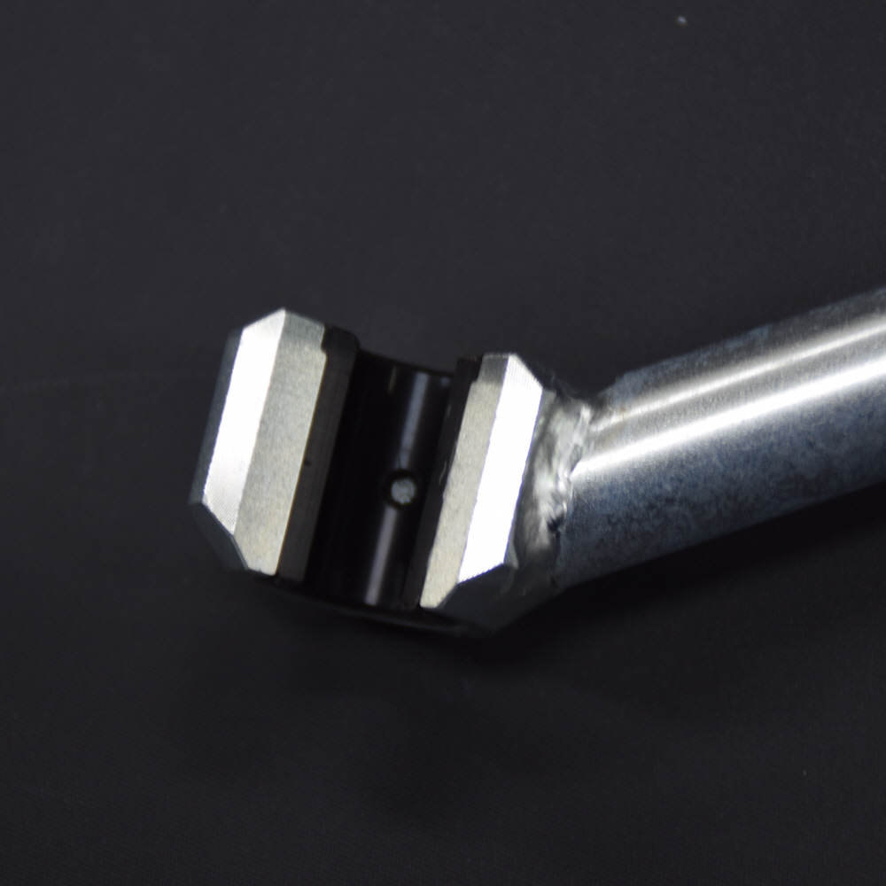
This is an anti-scratch hozel bending bar manufactured and supplied by FITTERSLAB.
It is a bending equipment manufactured by pressing a high-strength polymer resin insert
into the contact surface with the club hosel,
perfectly protecting the hosel from scratches during bending work.
Other bending bar products have a disadvantage in that the contact surface with the club is
mainly made of metallic materials such as aluminum or brass, causing indented marks or scratches
on the hosel surface during club bending work.
FITTERSLAB has supplemented this problem to supply a polymer resin insert-type bending bar
that does not cause any scratches on the hosel surface or shaft.
Due to the characteristics of polymer resin, indentation of the insert occurs during use,
but direct contact between the metal bending bar and the hosel does not occur.
Resin inserts can be purchased separately
VARIABLE ANGLE HOT MELT MACHINE
This is a head melt injection machine manufactured by FITTERSLAB
tailored to recent golf club trends
Unlike existing products that only allowed vertical injection,
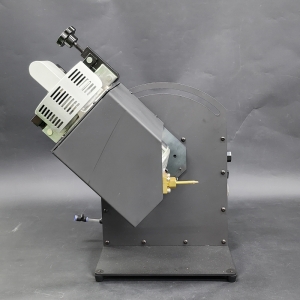
FITTERSLAB Variable Angle Head Melt Machine for golf clubs is a new type of
golf club head melt injection equipment designed so that
users can easily adjust the injection angle
according to the head shape for the first time in similar products.
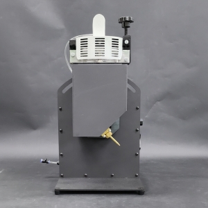
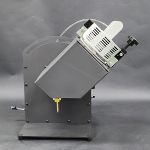
Recently, the application of sleeve and weight methods has become common for club heads.
Since this trend has diversified from the past sole reliance on injection through the hosel to
injection through separate melt holes or weight holes,
it has become very difficult for conventional equipment to respond to these demands.
Some major club makers are coping by using electric heating hose-type melt guns,
but due to the characteristics of the equipment being large, complex, and need a long preheating time,
it has the disadvantage of being very inconvenient to use
In particular, it can be considered very inappropriate equipment to use in fitting centers
where there is relatively little work.
FITTERSLAB Variable Angle Head Melt Machine is equipment developed by
design-wise solving these problems
so that it can be easily used not only by major club makers
but also by fitting centers and small workshops
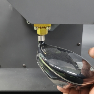
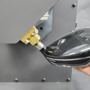
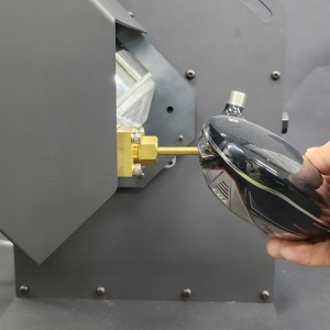
FITTERSLAB variable nozzle head melt machine is manufactured
so that the user can arbitrarily adjust the injection angle within a maximum 180-degree range,
consisting of a 90-degree area for each of types A, B, and C depending on the nozzle setting form
and a 90-degree variable area of the main body.
A. Specifications of Variable Nozzle Head Melt Machine
* Tank Capacity: 1,700 ml (Max)
* Operating Voltage: 220 VAC
* Heating Temperature: 300 degrees (Max)
* Adjustment Angle: 180 degrees (Max)
- Type A: 0 degrees to 90 degrees
- Type B: 45 degrees to 135 degrees
- Type C: 90 degrees to 180 degrees (Users can set each type)
B. Control Panel of the Variable Nozzle Head Melt Machine
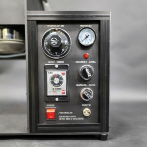
1. POWER: Operating power of the switch ON and OFF.
2. SWITCH (Switch Connection Terminal): A connection jack to the switch of the melt machine
3. MANUAL - AUTO (Manual-Auto Selection Switch): A switch operation into automatic and manual.
* Manual Mode: Injects continuously while holding down the injection switch.
* Auto Mode: Injects continuously for a set time on the timer regardless of the pressing time
whenever the injection switch is pressed.
4. AUTO-TIMER (Timer): Sets the injection time in seconds in AUTO mode.
5. EXHAUST - CHRG (Pneumatic Supply/Exhaust Switching): Used when applying pressure inside the tank
(CHRG) or releasing it (EXHAUST).
6. TEMPERATURE (Temperature Control): Sets the temperature of the tank.
7. PRESSURE (Pressure Gauge): A gauge that displays the pressure inside the tank linked with the regulator
-The regulator can be adjusted by lifting the knob and is fixed so it does not turn when pressed down.
C. Precautions When Installing the Head Melt Machine
1. Since the head melt machine is equipment heated to high temperatures,
it must be installed in a location with no flammable substances around it.
2. Since the tank angle is variable equipment,
sufficient clearance space of about 30 cm is required on each of the left and right sides.
3. Since the heat dissipation vents of the head melt machine
main body are located at the bottom and back of the equipment,
it must be installed so as not to block the vents
D. Installation of the Head Melt Machine
1. Install the head melt machine in a flat place.
2. Lightly tighten the injection nozzle only to the point where it stops turning,
as excessive tightening may damage the valve threads.
3. Push the pneumatic hose all the way into the pneumatic fitting to fasten it,
and set it to the appropriate pneumatic pressure using the upper regulator.
* Recommended pneumatic pressure is 0.3 to 0.5 MPa, and the higher it is set,
the greater the discharge amount.
4. Connect the power cord to 220V.
E. Filling the Melt
Since the head melt machine carries a risk of high-temperature burns,
safety goggles and heat-resistant gloves must be worn during use
1. Turn the EXHAUST switch to release the pneumatic pressure inside the tank.
* Opening the tank lid while pneumatic pressure is applied inside the tank will spew out heated air,
posing a risk of burns.
2. Loosen the angle adjustment knob at the rear of the tank,
turn the tank to the vertical position, and tighten the knob.
3. Release the clamp on top of the tank and open the tank lid.
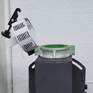

4. Put the melt block or melted melt material into the tank,
set the temperature switch to around 160 to 200 degrees, and turn on the power
The melt materials supplied by FITTERSLAB are provided in square block form,
Therefore, remove the protective layer and place it directly into the tank
However, when using products from other companies that are mainly supplied in cans,
It must be heated in an oven or similar to insertion
FITTERSLAB melt block can be easily cut by applying heat to a metal spatula
with a heating gun or gas torch.

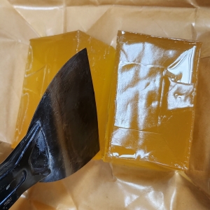

5. When the melt block is melted enough to close the lid, close the tank lid and tighten it firmly.
6. Turning the EXHAUST - CHRG button to CHRG makes it ready for use.
* More time may be required until the melt material inside the tank is sufficiently heated.
F. Information on Melt Materials
FITTERSLAB Variable Angle Head Melt Machine can use all melt materials
with a melting temperature between 100 and 250 degrees,
and products with a melting temperature of generally 160 to 200 degrees are suitable for golf club use.
Since the head melt machine of FITTERSLAB is shipped after actual use inspection
such as temperature and pressure tests for a certain period upon shipment,
a certain amount of melt material is filled in the product.
The tank capacity can be up to 1700 ml, but filling about 1/3 to 2/3 of the tank capacity is recommended.
The more material there is in the tank,
the longer the preheating time becomes and the more electricity is consumed
And due to the characteristics of the variable nozzle method,
filling it to the brim may cause the upper part to get smeared with melt and become sticky
during the next filling
How to Use and Precautions for the Melt Machine
G. How to Use the Variable Nozzle Head Melt Machine
1. Turn on the power switch and set the temperature switch to a temperature near 160 degrees.
When the heating heater operates, the pilot lamp on the instrument panel turns on,
and turning on and off is repeated to maintain the temperature.
2. Firmly lock the tank lid and turn the pneumatic switch in the "CHRG" direction to apply pressure
Check the pressure gauge for the tank pressure, and about 0.3 to 0.5 MPa is appropriate.
Pressure can be adjusted by lifting the regulator knob on the top of the main body
to set the pressure and then lowering the knob to fix it.
3. When the temperature rises sufficiently enough for the heating pilot lamp to turn off,
press the switch to check whether the melt material flows out smoothly,
and if it is not smooth even after long-term heating,
raise the temperature little by little to set it to a smooth temperature.
4. After heating sufficiently, adjust it to the desired angle and use
FITTERSLAB Variable Angle Head Melt Machine allow free adjustment of the injection angle
by type to 90° within a maximum range of 180°
A. 0° to 90° range
This is a method of using it by changing the angle in the vertical and horizontal injection regions
When prioritizing adhesion during a classic vertical feed, it is advantageous to set and use this area
B. 45° to 135° range
This is a method of using the angle by changing it in the classical injection method
If want to prioritize adhesion when applying upward, it is advantageous to set this area
C. 90° to 180° range
This is a method of using it by changing the angle, based on the classical injection method
It is advantageous to set this area when you want to prioritize adhesion
5. The discharge rate of the AUTO TIMER is not precise as it is affected by
the tank's temperature or pressure
For precise operation, recommend to use MANUAL mode and operate short and repeated cycles
6. Melting material on the outside can be removed by wiping with solvent or paint thinner
H. Precautions When Using
1. Since operating machinery is at high temperatures,
beware of burns and be sure to wear safety goggles and protective gloves.
2.Due to the characteristics of heating equipment,
the head melt machine consumes a lot of electricity,
and there is a risk of fire in case of overheating.
When not in use for a long time, please turn OFF the power
and release the pneumatic pressure with the EXHAUST button.
The pneumatic pressure inside the tank must be controlled with the regulator
and the EXHAUST button regardless of the power switch.
3. A tank temperature of around 160 degrees is appropriate,
and setting an excessively high temperature is prohibited due to the risk of ignition.
4. When releasing pressure, hot air may be momentarily discharged from the upper rear,
so please be careful of burns during operation
Main Uses and Applications of the Variable Nozzle Head Melt Machine
1. Adjustment of Swing Weight
Injecting melt material into the inside of the head to adjust the weight of the head and
accordingly the swing weight of the club can be considered the primary purpose of
using the head melt machine.
Unlike method of weighting the hosel portion like irons or wedges,
drivers and woods, hybrids etc, which have relatively small hosel spaces,
have a very narrow possible weighting range.
So the swing weight must be adjusted by injecting melt material.
In addition, even for products where weights are installed in the head
so that the head weight can be partially changed with the weights,
since the weight specifications are not subdivided,
it is difficult to cope with precise adjustment using only these weight specifications.
Since the head melt machine enables a wide range of weighting in fine units without these limitations,
even for head products equipped with weights,
recommend to adjust a large swing weight with the head's weights and
adjust the fine weight using the melt machine.
Since general melt materials from other companies are accompanied by changes in hitting sound,
injection within 8 grams is recommended in principle.
But the melt block developed and supplied by FITTERSLAB in partnership with a chemical company
does not spread excessively due to the suppression of expandability,
so the degree of reduction in hitting sound is small.
If not spread by applying heat, it can be used smoothly up to 15 grams without changes in hitting feel.
2. Prevention of Head Damage Risk Caused by High-Frequency Vibration
High-frequency vibration generated upon impact in all drivers, fairway woods, hybrids, etc.,
acts as a major cause of head cracks.
Since melt material has the effect of quickly absorbing such high-frequency vibrations
even in small amounts along with fine weight adjustment of the product,
a certain amount of melt material is essentially injected even during head production.
However, among heads supplied for fitting (custom) purposes,
many products are supplied without melt injected.
In such products, a certain amount of melt must be essentially injected along with
the adjustment of swing weight when manufacturing the club.
3. Correction of Hitting Sound
Depending on the head product,
there are many products the hitting sound is excessively loud or mixed with annoying off-sounds.
Such hitting sounds can be improved with melt material,
and in particular, the field of melt material in club fitting is spreading to an essential part,
to the extent that some enthusiasts even directly request the injection of melt.
The more melt material is put in and the wider it is spread, the greater the sound-quieting effect.
In the most common case for models with a head weight,
improvement can be made without changing the swing balance by replacing the weight
with a lighter product and injecting as much as that weight, but for fixed-weight products,
a slight swing balance change must be endured.
In this case, it is desirable to inject a small amount and then spread it as widely as possible
while heating the head for a certain period using an oven or the like.
The adhesion position of the melt material is in principle based on the bottom surface of the head.
While adhering it to the bottom surface minimizes changes in hitting sound,
adhering it to the crown portion increases the range of change,
making it a part where great effects can be expected with a small amount of material.
Toward the face surface side, changes not only in hitting sound but also in hitting feel become large,
so it is best to avoid it if possible.
4. Removal of Foreign Substance Sound Inside the Head
Melt material is also used to fix foreign substances when foreign substances
from head manufacturing fall off inside the head and make a sound.
Usually, after injecting about 1 to 2 grams of melt, shake the head immediately
to make the foreign substances stick to the melt for disposal.
After the foreign substances adhere and the sound disappears,
cooling causes the melt material to harden, allowing you to capture the off-sound.
At this time, it is effective to work by heating in an oven for about 10 to 15 minutes
so that the melt material sufficiently fixes the foreign substances,
and a slight increase in swing weight is accompanied by the weight of the melt material.
5. Use of Oven
It is convenient to use a head heating oven together with the melt injection equipment.
When want to spread the melt widely, after injecting the melt, placing the head in an oven and heating it
at about 160 to 180 degrees for about 10 to 15 minutes and then cooling it allows you to spread it widely
This method is particularly effective when you want to control the hitting sound through weighting
to avoid eccentricity or injection of a small amount.
However, caution is required as white-series heads or products with weak coatings
may not be able to use an oven due to heat discoloration issues,
and head products containing composite-system materials must never be heated in an oven
BENDING MACHINE FIXTURE
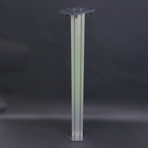
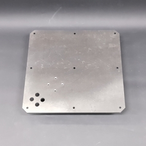
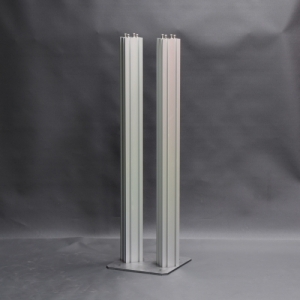
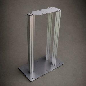
Mounting stand for FITTERSLAB Iron Bending Machines and Putter Bending Machines
A. FITTERSLAB Iron Bending Machine Stand
FITTERSLAB Iron Lie & Loft Bending Machine stand
This type is fixed to the floor using anchor bolts
B. FITTERSLAB Iron Bending Machine Plate
FITTERSLAB Iron Lie & Loft Bending Machine Plate
Reinforcement plate when installing equipment on the table without a separate stand
Secure it to the table using screws
C. FITTERSLAB Putter Bending Machine Stand
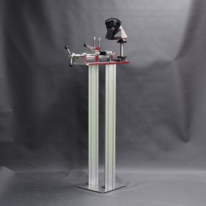
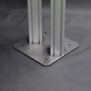
FITTERSLAB Putter Bending Machine Plate
This type is fixed to the floor using anchor bolts
D. FITTERSLAB Intergrated Bending Machine Stand
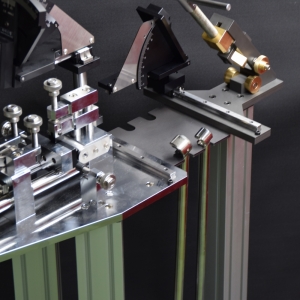
This is a fixed stand that supports both Iron Lie & Loft Bending Machine and Putter Bbending Machine
In principle, it is designed to be fixed to the floor using anchor bolts,
but since the equipment and the mounting stand are heavy,
using only silicone to attach the base plate works perfectly fine